In HF Propagation we described the extension of the scalar forward propagation equations (FPE) to accommodate HF propagation in the ionosphere where polarization effects important. Looking ahead to comparing full-field simulations to ray trace results we introduced ray tracing. In a delayed companion paper, Rino and Corrano currently in review, we introduced surface reflections to generate a complete vector forward propagation equation (VFPE). Accommodating surface reflections used an application of the forward approximation to surface scatter, Rino et al.
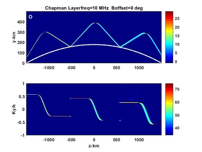
The following figure (Figure 4 in the paper) summarizes a VFPE realization. The upper frame is a static display of the field intensity evolving from and narrow upward point beam at z=-1500 km. The lower frame shows the spectral density of the field plotted against normalized spatial wave number, which is a measure of propagation direction. The upward trajectory is refracted by the ionosphere, redirecting the beam toward the earth’s surface where it is reflected. The details of the reflection are shown in the movie display.
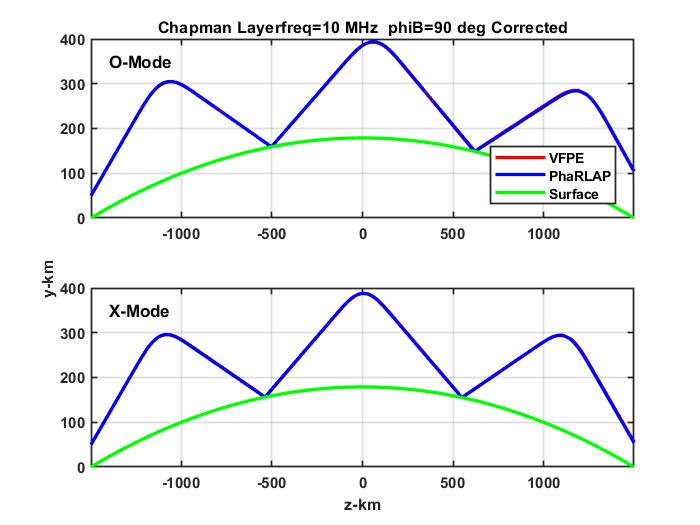
The figure below (Figure 8 in the paper) shows a comparison of trace of orthogonal polarized signal peaks with an overlay of the trace obtained from the PHaRLAP ray trace program as described in the paper. However, to get the agreement a correction to the VFPE was necessary. As described in the paper the was guess based sole on the behavior or the displacement as described in the paper. An argument was made as to why there should be a difference between a ray trace and realizations derived from the VFPE. The key element is the separate application of the propagation and refraction operations in each computation cycle. We expect further discussion and development of this new finding.